Cargo Handling Instructions
18 April 2025
TYPICAL HEAVY PROJECT CARGOES
CARGO INFORMATION
To be able to accept heavy project cargo, the following information must be available to secure and stow cargo properly:
- principal dimensions with drawings
- photos if available
- gross mass of the cargo
- location of the center of gravity
- bedding areas and particular bedding precautions
- lifting points or slinging positions
- securing points, including details of their location and MSL
LOCATION OF STOWAGE
When considering the stowage position for heavy project cargoes, the typical distribution of
accelerations on the vessel should be kept in mind. The lowest accelerations are found in the amidships sections on main deck.
Wheel based heavy cargoes shall be stowed in a fore-and-aft direction.
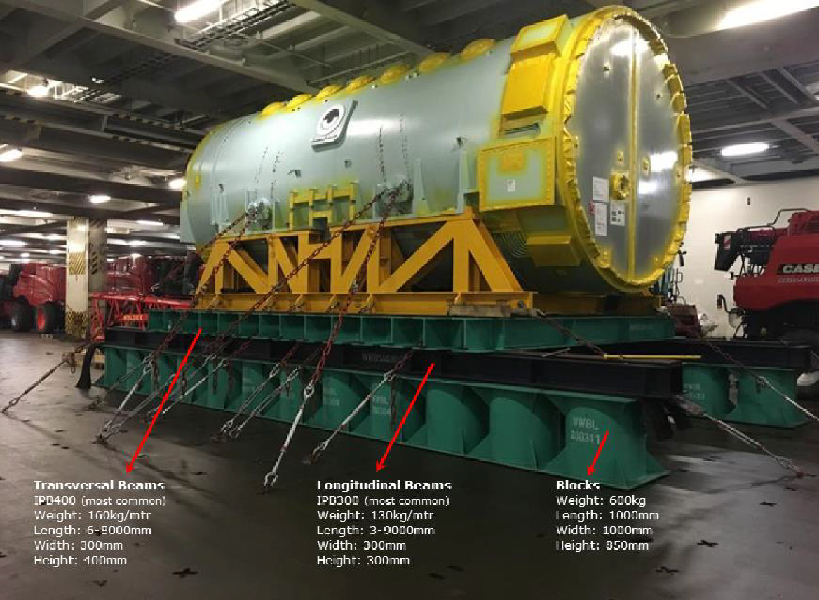
For some types of heavy project cargoes Blocks and Beams are used for the stowage onboard. This equipment consists of the items described in the figure below.
DISTRIBUTION OF WEIGHT
The weight of the cargo should be distributed in such a way as to avoid undue stress on the vessel's structure and suitable beams of adequate strength should be used to transfer the weight of the item onto the vessel's structure. If the maximum allowed deck load per m2 is exceeded special strength calculations should if deemed necessary be performed including instructions for stowage and bedding.
Consultation and approval shall be received from both BB Technical team and Marine Operations Management.
Timber or rubber should be used to increase friction between all surfaces where sliding could occur.
This does not apply to items on wooden cradles, on rubber tyres or with similar bottom materials having a built-in high coefficient of friction. Timber of approved type stamped according to IPPC (International plant protection convention) or hard wood to be used.
The securing devices should be so arranged as to withstand transverse and longitudinal forces and it shall prevent sliding and / or tipping in all directions.
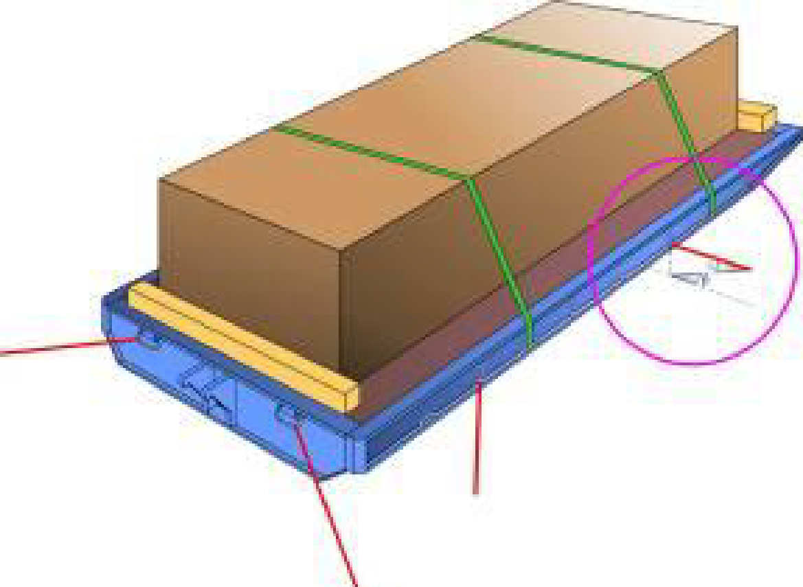
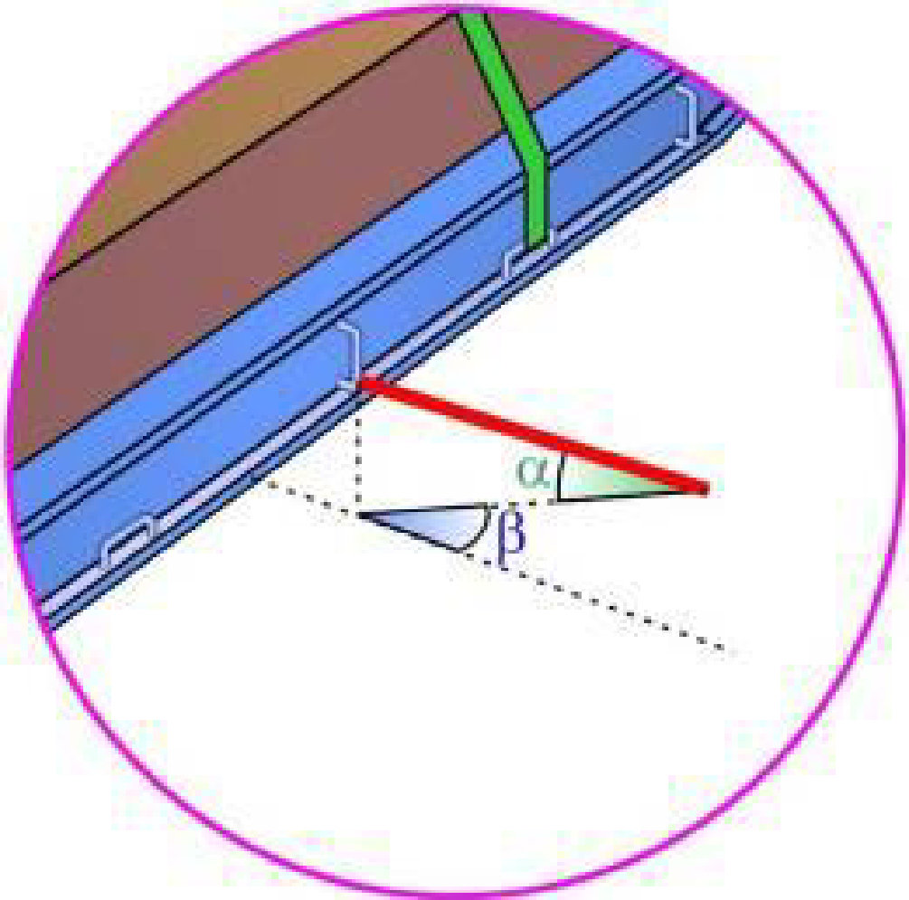
In the figures above the vertical lashing angle ɑ and the horizontal lashing angle β are shown. Most efficient prevention of sliding and tipping in different directions appears for the following values of ɑ and β:
| Value of α | Value of β | Most efficient in preventing |
|---|---|---|
| Small | Small | Transverse sliding |
| Large | Small | Transverse tipping |
| Small | Large | Longitudinal sliding |
| Large | Large | Longitudinal tipping |
The optimum vertical lashing angle against sliding is between 20° and 30°, while the optimum vertical lashing angle against tipping is generally found between 45° and 60° or larger. Optimum vertical lashing angle for lashings against both sliding and tipping is generally found between 30° and 60°.
Example of lashing arrangements
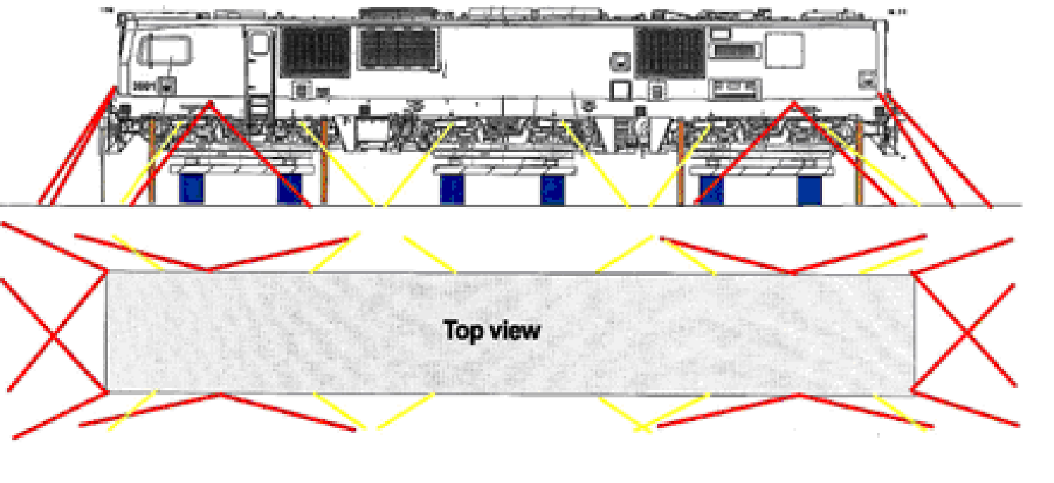
In the sketch above the red lines are showing heavy duty lashings with MSL 20 ton used on a 140-ton locomotive and the yellow lines show "normal" chain lashings with MSL 7,5 ton. From the sketch above, the vertical lashing angles β for all lashings are favorable to prevent both sliding and tipping, while the transverse lashing angles ɑ for most of the lashings are large and mainly preventing longitudinal sliding.
- Special arrangements and instructions are required for each loading/discharging performed by a "jack up" trailer. The OPERATORS representative shall issue those instructions.
- OPERATORS representative shall conduct a pre-plan meeting with the "jack-up" trailer operator together with Stevedores to review loading/discharging guidelines and procedures.